Raspberry PI 再起動後 Renogy Rover 40A に solarshed で通信できなくなってしまいました。。。
--
--
シリアル通信が拒絶されているように見えるのですが、solarshed の issue#15 で上がっている事象と同事象と思われます。
--
Suddenly Stopped Working #15 ,snichol67 opened this issue on 4 Nov 2021
I am all but certain that this is not an issue with Solar Shed. That being said, I had a perfectly working system running on a Raspberry Pi, everything was being stored in Prometheus, charted with Grafana. Then today, I reconnected my Renogy Bluetooth module just to see what the Renogy DC Home app could offer, just out of curiosity. Since I've done that, when I reconnect the Raspberry Pi Solar Shed server (and more specifically the MinimalModbus) library is reporting errors to the effect of:
Nov 03 13:22:19 raspberrypi python[445]: File "/home/pi/.local/lib/python2.7/site-packages/minimalmodbus.py", line 930, in _communicateNov 03 13:22:19 raspberrypi python[445]: raise IOError('No communication with the instrument (no answer)')Nov 03 13:22:19 raspberrypi python[445]: IOError: No communication with the instrument (no answer)
The software version on the charge controller is reporting device version V3.0.1 (I'm seeing this through the Renogy BT app on my phone). I'm starting to think that running the Renogy DC Home app might have updated the firmware on the device so that it somehow blocks requests over the serial port from unknown sources. Also just curious what the software version on your charge controller indicates?
--上記 issue に書かれているように、アプリで接続したときに勝手にファームが上げられてしまい、BT-1以外のシリアル通信(不明なソース)をブロックするようになってしまったのか?・・・原因は謎のままです。
ひとまず、新しいBT-1では、solar-bt-monitor が問題なく動作するので、新しいBT-1を取り寄せて Renogy Rover 40A も bluetooth で通信するようにしました。
・Renogy BT-1 Bluetooth モジュール ROVER シリーズ 3,100円(税送料込み)Renogy Solar Japan/Amazon
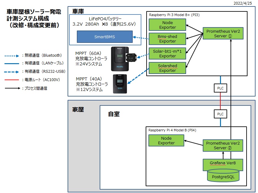
以下変更前。
以下変更後。
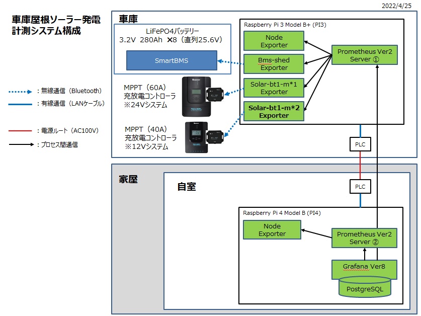
Renogy Rover 60A,40A,SmartBMS すべて Bluetooth 通信となった。
24Vシステムは変更なし。

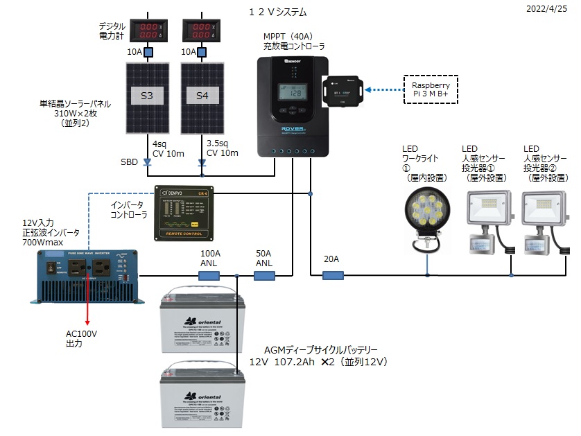
12Vシステムは、Renogy Rover 40A に新しいBT-1を接続した。
1.solar-bt1-monitor の追加
⇒Renogy Rover 60A用の solar-bt-monitor1 を solar-bt-monitor2 にコピーする。
# systemctl restart prometheus
5分程度 prometheus の再起動完了を待ってから
⇒solar-bt-monitor1、solar-bt-monitor2 はパラメータ名称("solarmon_solar_watts"の部分)が同じため"{instance="localhost:5002",job="solar-bt-monitor2"}"のようなインスタンス表記の追加で solar-bt-monitor1、solar-bt-monitor2 のパラメータを区別できるように、既存のダッシュボードについても変更の必要がある。
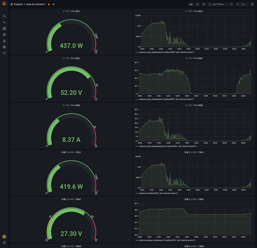
solar-bt-monitor2(12Vシステム 充放電コントローラ) のGrafana画面。


コメント